04/10/2020
Khuzema Darugar,
CADTech USA LLC
Scan-to-CAD is a form of reverse engineering that uses 3D scanners to create a digital copy of a physical object, to be used as a reference for recreating the physical object as a CAD model. Reverse Engineering is a method of reproducing an existing product by examining and measuring its construction and composition. It is a very broad term that can be applied to many branches of engineering. In this article we will delve into how reverse engineering is applied in the field of mechanical engineering and design. In this field, reverse engineering is the process of reconstructing an existing physical object in digital 3D by closely examining and measuring it.
For mechanical parts, based on the complexity of the geometry, traditional methods of measurement are not sufficient, and requires the use of a 3D scanner. In the case of this article, we have used our in-house Artec Space Spider to 3D scan a pump housing and reverse engineer it in Solidworks. The 3D scan and reverse engineering are for demonstration purposes only.
To reverse engineer the pump housing, we needed a high-resolution mesh which was achieved by using our 3D scanner in conjunction with Artec Studio. Once the scan was completed, the mesh was generated and aligned to the correct axis for export to the CAD software.
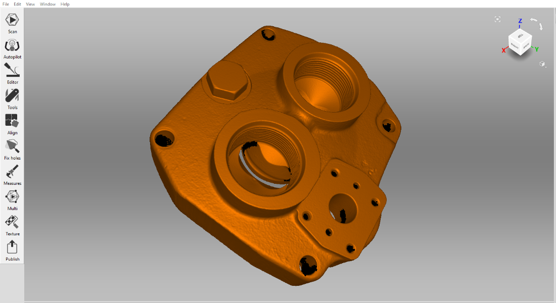
Scanned Pump Housing Lid Shown in Artec Studio
The key in reverse engineering a mechanical part, is to know how the part was produced, as it will determine how the part will be reverse engineered. For example, if a part was created by machining, then the part can be reverse engineered by visualizing how the part was machined. The geometry of a machined part will be limited to what can be achieved by removing material from the sides of the stock, as machining is a subtractive method. In contrast, a casted part can have complex internal geometry that sometimes cannot be seen from the outside. Features like this are possible as casting is an additive method. In addition to these two methods, there are numerous other ways to manufacture a mechanical part. By knowing how the part was manufactured, the engineer can get a better idea on the design intent that went into creating the original part.
For this project we used Solidworks and Xtract 3D to perform the reverse engineering. After importing the mesh into Solidworks, we checked if the mesh was aligned to the correct axis. Once the mesh was correctly setup, it was time to add the appropriate planes and axes needed for creating the model. After that, we started reverse modeling each feature by creating the proper geometry that best fit the mesh.
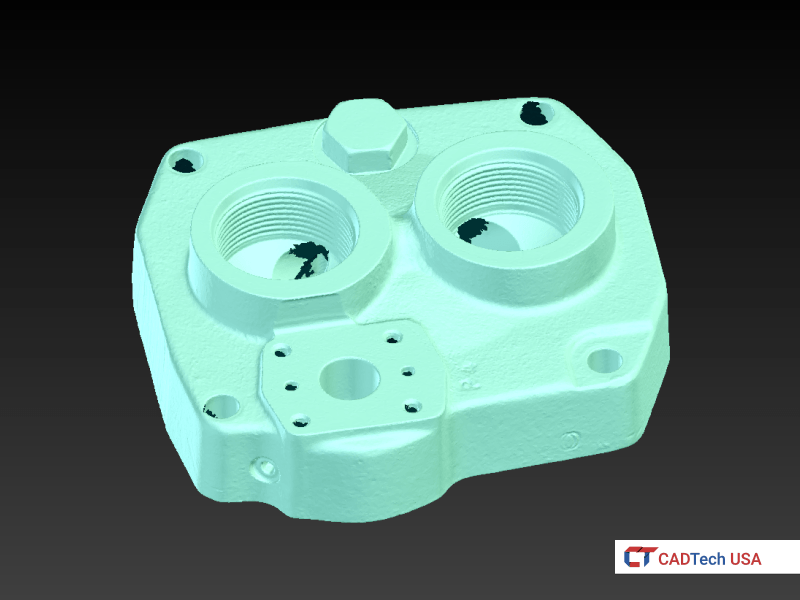 Scanned Mesh
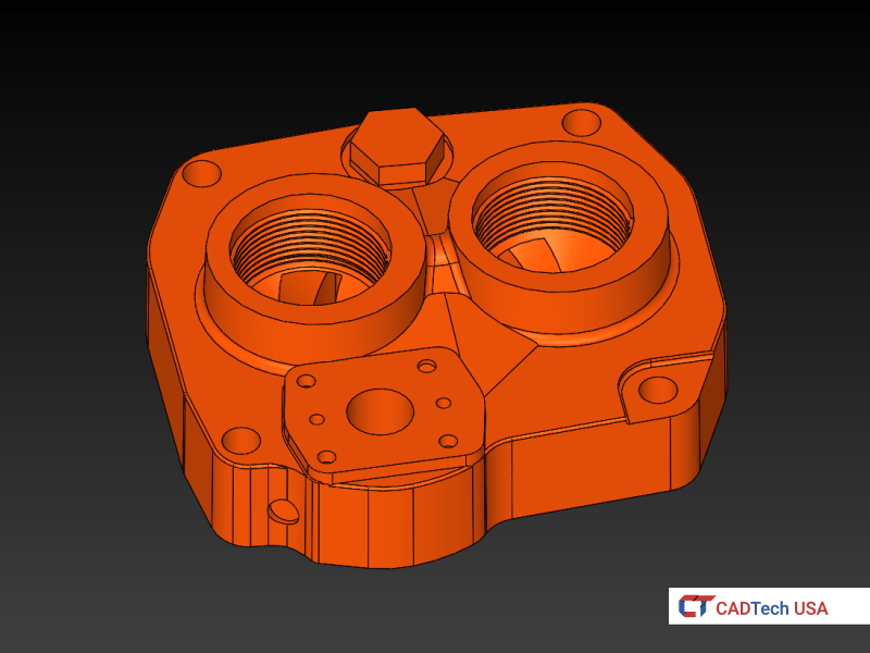 CAD Model
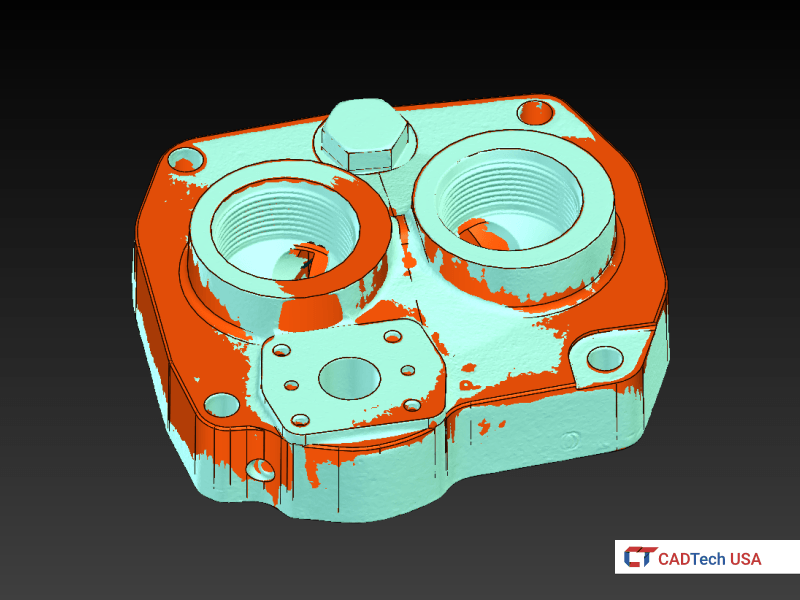
Scanned Mesh overlaid on Reverse Engineered Pump Housing Lid in Solidworks
During and after the reverse engineering process, one of the tools that we use is the deviation analysis feature. This feature provides us a color map which lets us identify the places where the model does not properly fit the scanned mesh. Once the color map from the deviation analysis gives us a sufficient result, the CAD model is ready for manufacturing. From there, depending on the customer’s needs, we can produce detail drawings for the part and a more detailed deviation analysis report.
 Scanned Mesh
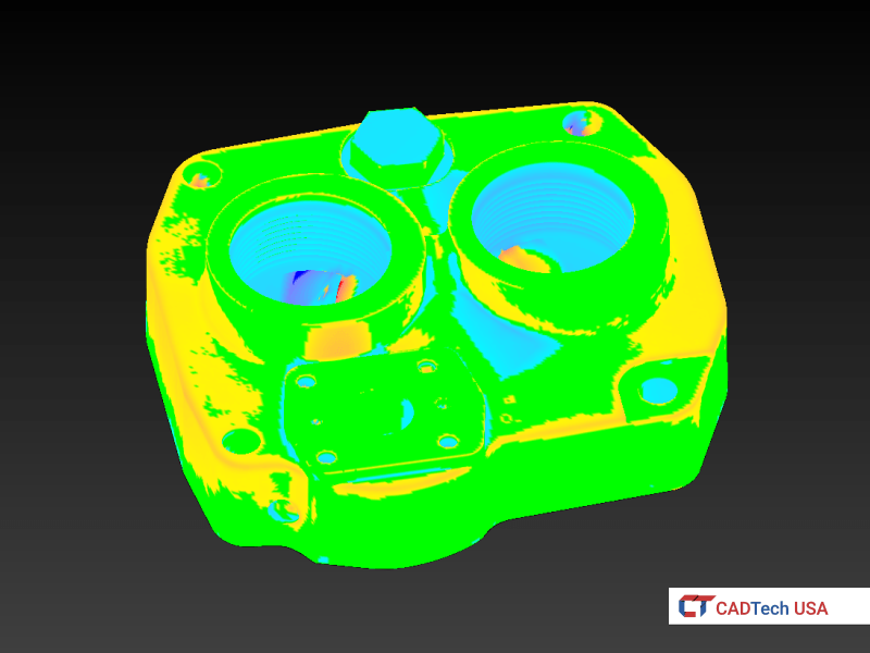 Deviation
Deviation Analysis on Scanned Mesh overlaid on Model in Xtract 3D
Below are a few more examples of mechanical parts being reverse engineered using the Scan-to-CAD approach.
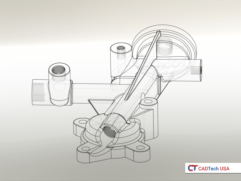
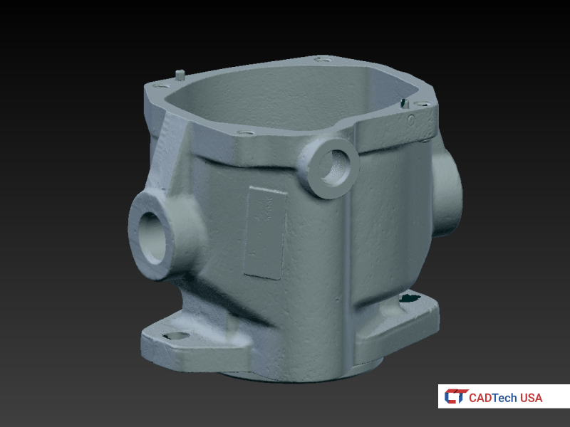 Scanned Mesh
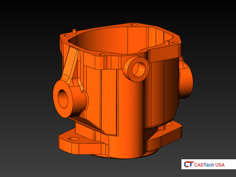 CAD Model
Scanned Mesh overlaid on Reverse Engineered Pump Housing in Solidworks
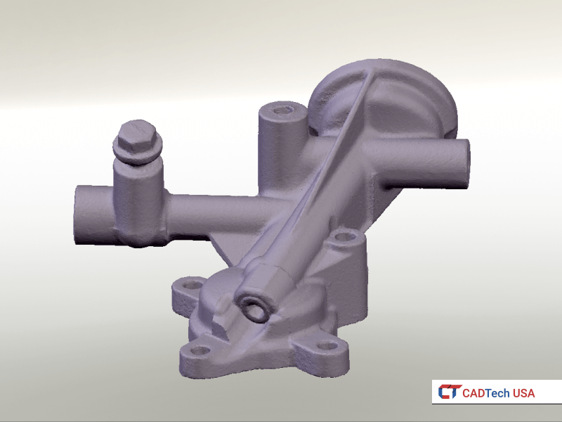 Scanned Mesh
 CAD Model
Scanned Mesh overlaid on Reverse Engineered Oil Manifold in Solidworks
Contact us if you have a project that requires Scan-to-CAD services for your parts or products.

